热门关键词:示例页面

刷空间_永久刷qq黄钻网站免费_哔哩哔哩在哪里买播放量
自助下单地址(拼多多砍价,ks/qq/dy赞等业务):点我进入
1、消防给水及消火栓系统
测试点1:消防泵的设置
(1)下列情况不得使用水泵:建筑高度小于54m的住宅建筑和室外消防给水设计流量小于等于25L/s的建筑; 室内消防给水设计流量≤10L/s。
(2)消防泵吸水管的布置要求:吸水管宜采用自吸式吸水。 吸水管采用管顶连接方式,吸水管异径管采用偏心异径管。 每台消防泵应设置独立的吸水管。 消防泵的吸入管路宜装明杆闸阀或带自锁装置的蝶阀。 消防泵的吸入管应装有压力表。 消防水泵吸入管穿过消防水池时,应采用柔性套管。
(3)消防泵出水管布置要求:每台消防泵应设置独立的出水管,并应设置不少于两根出水管与给水管或室内环形管网相接。 水泵出水管上应安装止回阀、闸阀或蝶阀和压力表。 出水管上还应安装DN65试水阀。
(4)消防泵的启动装置:消防泵的启动方式有自动启动和手动启动两种。 消防水泵由消防水泵出水管上的压力开关、高位消防水箱出水管上的流量开关或压力开关直接自动启动。的报警阀。 消防泵房压力开关应引入消防泵控制柜。 消火栓按钮不应作为直接启动消防泵的开关使用,但可作为发出报警信号的开关或启动干式消火栓系统的快速启闭装置。 稳压泵由设置在消防供水管网或气压水箱上的自动启停泵压力开关或压力变送器控制。
(5)室内消防给水管道安装:室内消火栓系统管网宜呈环状布置。 当室外消火栓设计流量不大于20L/s(建筑高度超过50m的住宅建筑除外),且室内消火栓不超过10个时,可分支布置。 室内消火栓立管管径按立管最小流量计算确定,但不应小于DN100。 室内消火栓立管应保证管道检修时停用的立管不超过1根。 当立管超过4根时,可关闭不相邻的2根; 应设置阀门。 室内消火栓给水管网应与自动喷水灭火等其他水灭火系统管网分开设置; 消防泵配套使用时,供水管路应沿水流方向单独设置在报警阀前。 高层民用建筑室内消防给水系统的管路,应当与生活、生产给水系统分开设置。 室内消火栓给水管一般采用热镀锌钢管。
测试点二:减压阀的设置要求
减压阀设置要求:减压阀应安装在报警阀组进口前。 当连接两个或多个报警阀组时,应安装备用减压阀。 减压阀进口处应安装过滤器,过滤器和减压阀前后应安装压力表,过滤器前、减压阀后应安装调节阀。 减压阀后应安装试压泄水阀。 垂直安装的减压阀,水流方向应向下。 比例减压阀应垂直安装,可调式减压阀应水平安装。
测试点三:水泵适配器安装位置
1)高层民用建筑; 2)有消防给水的住宅和其他五层以上的多层民用建筑; 3)2层以上或建筑面积大于10000平方米的地下或半地下建筑物(室)及室内消火栓设计流量大于10L/s的人防组合工程; 4)高层工业建筑和四层以上的多层工业建筑; 5)城市交通隧道。 自动喷水灭火系统、水喷雾灭火系统、泡沫灭火系统、固定式火炮灭火系统等水灭火系统,应配备消防泵接头。
测试点4:调节泵设计压力
稳压泵的设计压力应满足自动启动和管网充满水的要求; ②稳压泵的设计压力应使系统自动启泵压力设定点的压力大于系统在准工作状态下设定的自动泵压力值,增加值应为0.07MPa-0.10MPa; 稳压泵的设计压力应使准工作状态下系统最不利点处水灭火设施的压力大于该处的静水压力,其增加值不应小于0.15MPa。
测试点4:调节泵设计压力
1)稳压泵的设计流量应符合下列要求:
①稳压泵的设计流量不应小于消防给水系统管网正常泄漏率和系统自动启动流量;
②消防给水系统管网的正常泄漏量应根据管道材质和接口形式确定。 不应小于1L/s;
③消防给水系统用报警阀压力开关的自动启动流量应根据产品确定。
2)稳压泵的设计压力应符合下列要求:
①稳压泵的设计压力应满足系统自动启动和管网注水的要求;
②稳压泵的设计压力应使系统自动启动泵压力设定点的压力高于系统在准工作状态下设定的自动启动泵压力值,增加值应为0.07MPa~0.10MPa;
③稳压泵的设计压力应使系统最不利点的水灭火设施在准工作状态下的静水压力大于0.15MPa。
重点分析
图3-1-18 稳压泵设计压力的确定(一)
①稳压泵的启动压力为P1>15-H1,且≥H2+7。
②稳泵停泵压力P2=P1/0.80。
③ 消防泵启动压力P=P1+H1+H-7。
图3-1-19 稳压泵设计压力的确定(二)
①稳压泵启动压力P1>H+15,且≥H2+10。
②稳泵停泵压力P2=P1/0.85。
③ 消防泵启动压力P=P1-(7~10)。
④稳压泵从高位水箱吸水时,提示1~3参数仍然适用,但稳压泵壳的承压能力不应小于泵的1.5倍停止压力P1。
4)带稳压泵的临时高压消防给水系统应有防止稳压泵频繁启停的技术措施。 当采用气动水箱时,其调节容积应按稳压泵的启动和泵送次数不大于15次/h计算确定,但有效储水容积不应小于150L。
5)稳压泵吸入管宜装明杆闸阀,稳压泵出口管宜装消声止回阀和明杆闸阀。
6)稳压泵应设备用泵。
测试点5:火池
(1)消防水池设置位置: ①当生产生活用水量达到最大时,市政供水管网或进水管不能满足室内外消防用水量; ② 消防给水采用一根或只有一根进水管时,且室外消火栓设计流量大于20L/s或建筑高度大于50m时; ③市政消防给水设计流量小于建筑物。
(2)消防水池设置要求:当消防水池总有效蓄水量大于500m³时,宜设置两个可独立使用的消防水池,并设置一个应设置满足最低有效水位的连接管; 但大于1000m³时,宜设置两个可独立使用的消防水池。 每个消防水池应设独立的出水管和满足最低有效水位的连接管。 对于消防水池,当消防水与其他水混合使用时,应有技术措施保证消防水不被他人使用。 火池补水时间不应超过48小时。
测试点6:消防用水量计算
(1) 火灾持续时间
A、B、C类厂房、仓库:3.0h; D类和E类工厂和仓库:2.0h。
商业建筑、展览建筑、高层建筑中的综合建筑、建筑高度大于50m的金融金融建筑、图书馆、书库、重要档案建筑、科研建筑和高档宾馆:3.0h; 其他公共建筑和住宅:2.0h
(2)建筑物内用于防火分隔的防火分隔水幕和防护冷却水幕的耐火持续时间不应小于设置防火分隔水幕或防护冷却防火幕的墙体的耐火极限。
(3) 当自动喷水灭火系统、喷水灭火系统、泡沫灭火系统或固定式火炮灭火系统等一套或多套自动水灭火系统在室内得到充分保护时,高层建筑的高度不应超过50m且室内消火栓设计流量超过20L/s的,室内消火栓设计流量可按规范降低5L/s; 多层建筑室内消火栓设计流量可减少50%,但不应小于1OL/s。
测试点七:高火水箱
(1)在室内使用临时高压消防给水系统时,高位消防水箱的设置应符合下列规定: ①高层民用建筑、总建筑面积大于10000平方米的公共建筑平方米及2层以上等重要建筑物必须配备高位消防水箱。 消防水箱; ②其他建筑应设置高位消防水箱,但设置高位消防水箱确有困难,又采用安全可靠的消防供水形式时,高位可不设消防水箱,但应设稳压泵; ③当市政供水管网供水能力满足生产、生活每小时最大用水量,且仍能满足初期火灾所需的消防流量和压力时,可采用市政直供水替代高位消防水箱。
(2) 高火水箱的有效容积和静水压力
注:①当店铺建筑不符合一级高层公共建筑规定时,取最大值。
②当高位消防水箱不能满足本表静压要求时,应设置稳压泵。
测试点八:室外消火栓系统
室外消火栓应均匀布置在建筑物四周,不应集中在建筑物的一侧; 建筑物消防面一侧的室外消火栓数量不应少于2个。
测试点九:室内消火栓系统
(1)当室内环境温度不低于4℃且不高于70℃时,宜采用湿式室内消火栓系统。 室内环境温度低于4℃或高于70℃的场所,宜采用干式消火栓系统。 建筑高度不大于27m的多层住宅,如在室内安装湿火探测系统确有困难,可设置干火立管。
(2)干式消火栓系统充水时间不应超过5分钟,并应符合下列要求:主供水管; 使用电动阀时,开启时间不应超过30s; ②使用雨淋阀、电磁阀、电动阀时,应在消火栓箱处设置直接开启速闭装置的手动按钮; ③系统管道的最高点应设置快速排气阀。
(3)宜采用DN65室内消火栓,可与消防水带卷盘或手提水带设置在同一箱内。 应配置公称直径为65mm的内衬消防水带,长度不超过25.0m; 应配置喷嘴当量直径为16mm或19mm的消防水带。
(4)设有室内消火栓的建筑物,包括设备层在内的所有楼层均应设置消火栓。 室内消火栓布置应满足同一平面上两个消防水嘴的两个满水柱同时到达任一部位,但建筑高度小于或等于24.0m且容积为小于或等于高度为54m,每单元1个疏散楼梯的住宅,按《消水规程》表3.5.2规定可使用1个消防喷头的,1个满水柱消防喷嘴可用于到达房间的任何部分。
(5)室内消火栓布置间距宜按直线距离计算。 消火栓按两个消防水嘴两个满水柱布置的建筑物,消火栓布置距离不宜大于30.0m; 满水柱布置的建筑物,消火栓的布置间距不应大于50.0m。
(6)消火栓口动压力不应大于0.50MPa。 大于0.70MPa时,必须加装减压装置。 高层建筑、厂房、仓库、室内净空高度超过8m的民用建筑,消火栓动压不应小于0.35MPa,消防水嘴水柱应达到13m; 其他地方消火栓的动压不应小于0.25MPa,消防水嘴满水柱应达到10m。
测试点10:小区供水
(1)当满足下列条件时,消防给水系统宜分区域供水: ①系统工作压力大于2.40MPa; ②消火栓处静压大于1.0MPa; 喷嘴处工作压力大于1.20MPa。
(2) 区域供水形式可采用并联或串联消防水泵、减压水箱、减压阀减压的形式,但当系统工作压力大于2.40MPa时,消防水泵形式宜采用串联或减压水箱分区供水。
(3)采用消防泵串联分区域供水:采用消防泵串联调水箱时,调水箱的有效蓄水容积不应小于60m³,调水箱可用作高位消防水箱。 串联转移罐的溢流管应与消防水池相连。 消防泵应能从低区到高区依次启动。 串联消防泵出口管路应安装减压式倒流防止器。
(4)采用减压阀对不同区域供水减压时:每个供水区域应配备不少于2套减压阀,每套减压阀应配备1个备用减压阀. 减压阀只宜设置在单向流供水管上,不应设置在双向流供水总管上。 减压阀宜采用比例减压阀,超过1.20MPa时,宜采用先导式减压阀。 减压阀阀前后压力比不应大于3:1。 当一级减压阀的减压量不能满足要求时,可用减压阀串联减压,但串联减压量不应大于二级。 一级减压阀宜采用先导式减压阀,阀前后压差不应超过0.40MPa。 减压阀后应安装安全阀。
(5)采用减压水箱进行减压分区:减压水箱的有效容积不应小于18立方米,应分为两个隔室; 减压水箱应有进出水管两路,各进出水管应满足消防给水系统要求的消防给水系统要求; 减压水箱的进水管应设有防震、防溢流技术措施,并在进水管上设置紧急切断阀,溢流水应回流到消防水池。
测试点十一:管网压力测试
(1)当系统设计工作压力等于或小于1.0MPa时,水压强度试验压力应为设计工作压力的1.5倍,且不应低于1.4MPa; 当系统设计工作压力大于1.0MPa时,水压强度试验压力为工作压力加0.4MPa(钢管);
(2)水压强度试验的试验点应设置在系统管网的最低点。 向管网注水时,应排尽管网内的空气,缓慢升压。 达到试验压力并稳压30分钟后,管网无渗漏、无变形压力表安装转接头,压降不大于0.05MPa;
水压强度试验和管网冲洗合格后,进行水压密性试验。 试验压力为设计工作压力,稳压24小时应无泄漏;
(3)气压密性试验应采用空气或氮气作为介质,试验压力为0.28MPa,稳压24小时,压降不应大于0.01MPa。
考点十二:系统维护与管理
消防泵应每周自动启动一次,模拟消防泵自动控制情况,自动记录自动巡检情况,每月核对记录; 每月应手动启动消防泵一次,并检查电源。 每月检查一次气压水箱的压力和有效容积。 每季度应检测一次消防泵的输出流量和压力。
每季度对系统所有末端试水阀和报警阀的试水阀进行一次试水,检查系统启动、报警功能和出水是否正常。
2、自动喷水灭火系统
温馨提示:本系统历年考试重点,强烈推荐阅读《自动喷水灭火系统设计规范GB50084-2017》
测试点一:火灾危险等级
考点二:喷头选择
① 安装封闭系统的场所,喷头型式及场所最大净空高度应符合下表要求
②湿式自动喷水灭火系统,不采用吊顶的,配水支管布置在梁下时,应采用立式喷头; 吊顶下布置的洒水喷头宜采用悬垂式洒水头或吸顶式洒水头; 侧墙式洒水喷头可用于具有轻度危险等级和中危险等级Ⅰ的水平屋面的住宅楼、宿舍楼、宾馆楼客房、病房和医疗楼办公室; 对于容易发生碰撞的部位,宜采用带防护罩的洒水喷头或吸顶式洒水喷头; 屋面水平且无横梁、通风管等障碍物影响洒水喷头的,可采用扩大覆盖面积的洒水喷头; 居住建筑和宿舍、公寓等非居住建筑应当使用家用洒水喷头; 不应使用隐藏式洒水器; 必要时,仅可用于轻度、中度危险的Ⅰ类场所。
③ 采用快速反应洒水喷头时,系统应为湿式系统。 下列场所宜使用快速反应洒水喷头:公共娱乐场所、中庭环廊; 医院、疗养院病房、治疗区,老人、儿童、残疾人集体活动场所; 超出消防泵接头供水高度的楼层; 地下商业场所。
④ 对于封闭系统的喷嘴,其标称工作温度应比最高环境温度高30℃。 同一隔间内应使用热力性能相同的洒水喷头。
测试点三:喷嘴安装
(1)干式系统活性面积按表中规定值的1.3倍确定。 系统最不利点的喷嘴工作压力不应低于0.05MPa。
民用建筑和工业厂房系统设计基本参数
(2)民用建筑高大空间湿式系统设计基本参数
(3)同一配水支管上的喷嘴间距和相邻配水支管的间距
(4)液压警铃宜设在有人值班的地方附近,与报警阀相连的管路直径宜为20mm,总长度不应大于20m;
一个报警阀组控制的喷嘴数量,湿式系统和预作用系统不宜超过800个,干式系统不宜超过500个。 各报警阀组最高与最低供水喷嘴的高差不应大于50m。
测试点四:功能检查
(1) 水流指示器
检查要求:①检查水流指示器的灵敏度。 试验压力为0.14MPa-1.2MPa。 当流量不大于15.0L/min时,水流指示器不报警; 流量在15.0L/min-37.5L/min任意值时报警,达到37.5L/min时报警。 ②带延时功能的水流指示器,查看桨叶动作后的报警延时时间,范围为2s-90s,不可调。
(2)终端试水装置
检验要求:①测试末端试水装置的密封性能,试验压力为额定工作压力的1.1倍,保压时间为5分钟,末端试水装置试水阀关闭,有试验结束时末端试水装置各部件无渗漏现象。 ②终端试水装置手动(电动)操作方式灵活,开启方便。 信号反馈装置可在终端试水装置开启后输出信号。 试水阀关闭后,末端试水装置无渗漏。
测试点五:联动调试与测试
(1)报警阀调试
1)报警阀的调试应符合下列要求:
① 湿式报警阀调试时,在末端装置放水。 当湿式报警阀进水压力大于0.14MPa,出水流量大于1L/s时,应及时启动报警阀; 带延时器的液压警铃应在5s~90s内响铃,15s内响铃,不带延时器的液压警铃应在15s内响铃; 压力开关应及时动作,启动消防泵并反馈信号。
②调试干式报警阀时,打开系统试验阀,报警阀启动时间、起点压力、水流到试验装置出口所需时间均应符合设计要求.
③ 雨淋阀调试应采用试探、试管等方式进行。 自动和手动启动的雨淋阀应在15秒内启动; 公称通径大于200mm的雨淋阀,调试时应在60s内启动。 雨淋阀调试时,当报警水压为0.05MPa时,水力报警铃应发出报警声。
④ 预作用装置的调试应根据湿式报警阀组和雨水报警阀组的调试要求进行综合调试。
2)联动试验应满足以下要求:
① 湿式系统联动试验,当一个喷头启动或末端试水装置放水时流量为0.94L/s~1.5L/s,水流指示器、报警阀、压力开关、液压警铃、消防泵等压力表安装转接头,应及时动作,发出相应信号。
② 预作用系统、雨淋系统、水幕系统的联动试验,可采用专用测试仪器或其他方法,向火灾自动报警系统各探测器输入模拟火灾信号,火灾自动报警控制器应发出声光报警信号,启动自动喷水灭火系统; 输水管启动的雨淋系统与水幕系统联动试验时,启动一个喷头,打开雨淋阀,系统管网压力开关或高位消防水箱流量开关启动,消防水泵启动,并有相应的元件信号反馈。
③干式系统联动试验,系统控制装置设置为“自动”控制方式,启动一个喷头或模拟一个喷头的排气、报警阀、压力开关、高位消防水箱流量开关、水力警铃、压力应及时启动系统管网开关和消防泵,并发出相应信号。
测试点六:年检
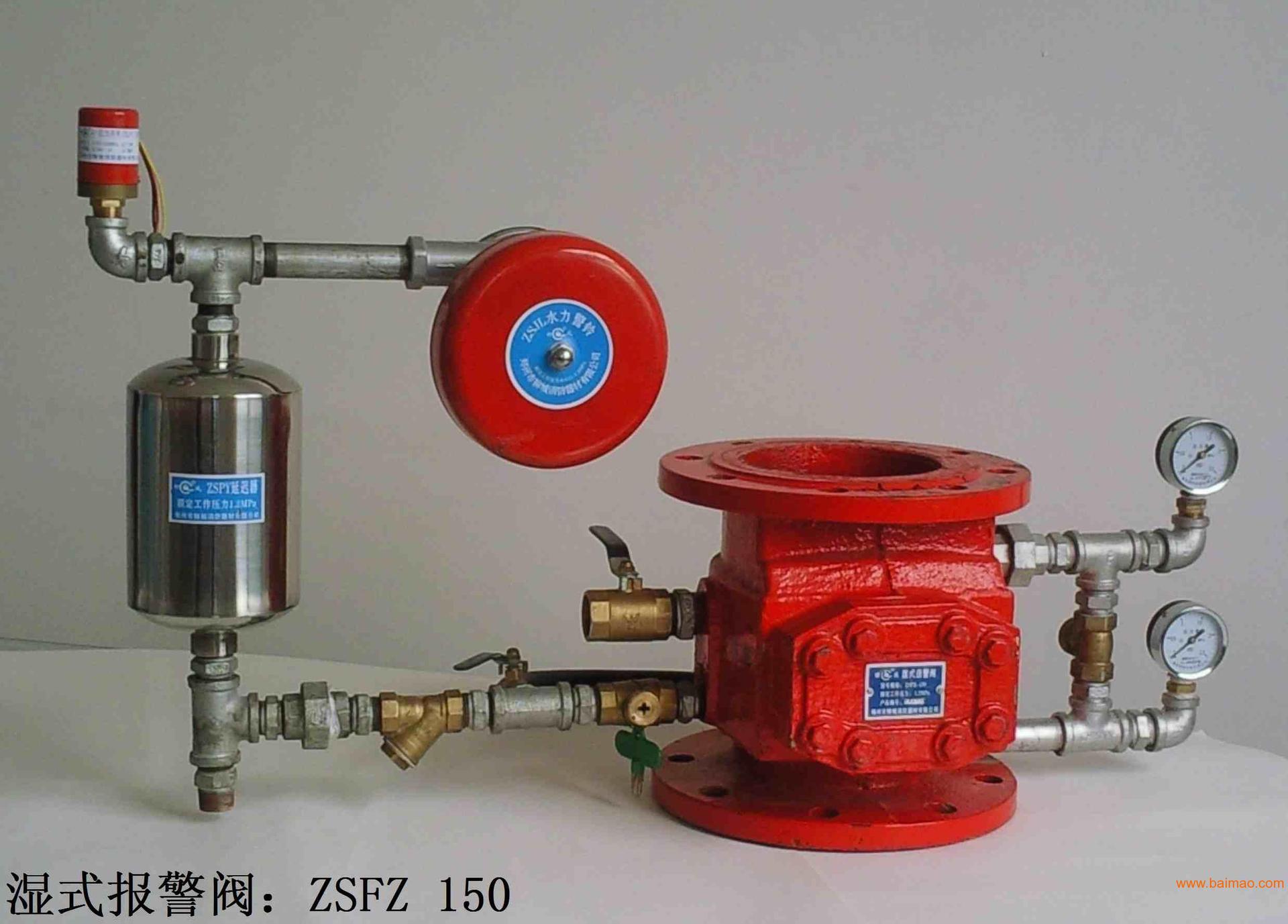
(一)湿式报警阀组检测操作步骤
① 开启系统末端(区)试水装置前,检查并记录压力表读数; 最后打开试水装置,待压力表指针平稳抖动后,检查并记录压力表的变化。 出水压力不应低于0.05MPa。
②检查消防设备显示的水流指示器、压力开关、消防泵的动作及信号反馈情况。
③从末端试水装置开启,消防泵投入运行开始计时,时间在5分钟以内。
④ 在距液压警铃3m处,用声级计测量液压警铃的声强,不应低于70dB。
⑤ Turn off the terminal water testing device, reset the system, and return to the working state.
(2) Operation steps for detection of dry alarm valve group
①Slowly open the test valve of the air pressure control device, and discharge air with a small flow rate; after the air compressor starts, close the test valve, check the operation of the air compressor, and check its start and stop pressure.
②Open the control valve of the water test device at the end, check and record the changes of the pressure gauge as above.
③ Check the fire control equipment, exhaust valve, etc., check the actions of the water flow indicator, pressure switch, flow switch, fire pump, electric valve at the inlet of the exhaust valve and their signal feedback, as well as the exhaust condition of the exhaust valve.
④Time from when the terminal water test device is turned on, and after 1 minute of opening the terminal water test device, the outlet water pressure must not be lower than 0.05 MPa.
⑤Measure the strength value of the hydraulic alarm bell according to the requirements of the wet alarm valve group. The hydraulic alarm bell shall be used for alarm, and the intensity value of the hydraulic alarm bell shall not be lower than 70dB.
⑥Turn off the water testing device at the end, reset the system, and return to the working state.
(3) Operation steps for detection of pre-action alarm valve group
①Slowly open the test valve of the air pressure control device, and discharge air with a small flow rate; after the air compressor starts, close the test valve, check the operation of the air compressor, and check its start and stop pressure.
②Close the control valve at the inlet of the pre-action device, the fire control equipment outputs the control signal of the solenoid valve, check the action of the solenoid valve, and check the accuracy of the feedback signal.
③According to the design linkage logic, simulate 2 different types of fire detection and alarm signals in the same protection area, check the fire alarm, confirmation and linkage command issued by the fire alarm controller, and check the pre-action device (deluge alarm valve) and solenoid valve one by one , electric valve, water flow indicator, pressure switch and fire pump action, and exhaust valve exhaust.
④Measure the sound intensity of the hydraulic alarm bell according to the requirements of the wet alarm valve group, and it shall not be lower than 70dB.
⑤ Turn on the water testing device at the end. After the fire controller confirms the fire for 2 minutes, read and record the value of the pressure gauge, and the water outlet pressure should not be lower than 0.05MPa.
⑥ Check the fire alarm controller, corresponding to the start-up of each component on site, check the action signals of solenoid valves, electric valves, water flow indicators and fire pumps, and the feedback signals are accurate.
⑦Turn off the water testing device at the end, reset the system, and return to the working state.
(4) Detection operation steps of rain alarm valve group
①For the deluge alarm valve group controlled by the transmission pipe, check and read the value of the pressure gauge of the transmission pipe, and check the pressure setting value of the transmission pipe; The air pressure control device is tested.
②Inspect the on-site control equipment and the fire control equipment in the fire control room respectively, and check the control mode of the deluge alarm valve group.
③ For the deluge alarm valve group controlled by the transmission pipe, close the control valve on the side of the alarm valve system before the test, perform pressure relief operation on the transmission pipe, and check the actions of the alarm valve, solenoid valve, pressure switch and fire pump one by one.
④ For the deluge alarm valve group controlled by the fire detector, close the control valve on the side of the alarm valve system before the test, simulate two types of different fire detection and alarm signals in the same protection area, and check the fire alarm, confirmation and linkage of the fire alarm controller Instructions are issued, and the actions of alarm valves, solenoid valves, pressure switches and fire pumps are checked one by one.
⑤ When setting multiple deluge alarm valves in parallel, follow the steps of "③" or "④" to test in different protection areas, and observe the action of the deluge alarm valve group and its components corresponding to each protection area.
⑥Measure the sound intensity of the hydraulic alarm bell according to the requirements of the wet alarm valve group, and it shall not be lower than 70dB.
⑦ After the alarm valve group operates, check the start-up of the on-site solenoid valve, fire pump and pressure switch, and check their feedback signals and linkage control logic relationship.
⑧ For the water curtain system controlled by manual operation, close the water source control valve, and manually open and close the system control valve on site repeatedly.
⑨Reset the system and return to the working state.
(5) Detection operation steps of terminal water test device
① Check the appearance of the valves, pressure gauges, water test joints and drain pipes of the terminal water test device on site.
②Close the water testing device at the end, read and record the value of the pressure gauge.
③Open the control valve of the water testing device at the end, and read and record the value of the pressure gauge after the pointer of the pressure gauge shakes stably.
④ After the water pump starts automatically for 5 minutes, read and record the value of the pressure gauge, and observe its changes.
⑤ Turn off the terminal water testing device, reset the system, and return to the working state.
Test point 7: Troubleshooting
(1) Analysis of the cause of the water leakage failure of the alarm valve group: ①The drain valve is not completely closed. ② Disc gasket is aging or damaged. ③ Leakage at the pipe interface on the system side. ④Alarm pipeline test control valve leakage. ⑤ There is a leaky state between the disc assembly and the valve seat due to deformation or dirt and sundries.
(2) Cause analysis of hydraulic alarm bell not working normally: ① product quality problem or installation and commissioning does not meet the requirements. ②The control port is blocked or the hammer mechanism is stuck.
(3) When the test valve is opened, the fire pump cannot start normally. Analysis of the cause of the failure: ①The setting value of the pressure switch is incorrect. ② The control module in the fire linkage control equipment is damaged. ③The control mode of the water pump control cabinet and linkage control equipment is not set in the "automatic" state.
(4) The system test does not alarm, and the cause of the failure is analyzed: ① Impurities in the fire-fighting water block the filter screen of the filter on the alarm pipe. ②The nozzle at the water inlet of the hydraulic alarm bell is blocked, the bell hammer is not equipped or the bell hammer is stuck.
(5) Analysis of the cause of the failure of the water flow indicator: ①The paddle is blocked by debris in the lumen. ②The adjustment nut and contact are not adjusted in place. ③The circuit wiring is disconnected.
相关资讯
热销产品
同类文章排行
- 快手一元1000个赞秒到_卡盟平台_拼多多新人助力网站
- 和平小号网_拼多多助力网站在线刷免费_3元抖音小号批发网
- 刷网课代理_快手永久免费秒赞秒评软件_刷会员
- 一秒1w粉丝app_24小时全自助下单网站播放量_微博刷赞器
- qq会员秒拿5000成长值自助站_刷课网站_快手互赞软件免费
- 刷王者点卷的网站_qq互赞网站平台_拼多多免费助力网站
- qq-shuazan_抖音粉丝1元1000粉_快手粉丝-元100个不掉粉
- 免费领取500个微博粉丝_王者卡盟_快手粉丝-元100个不掉粉
- 拼多多砍价一毛十刀网站_猪猪网站_拼多多助力刷人软件
- 快手代刷网站_小柯秒赞网_qq刷钻
最新资讯文章
- 快手一元1000个赞秒到_卡盟平台_拼多多新人助力网站
- 和平小号网_拼多多助力网站在线刷免费_3元抖音小号批发网
- 刷网课代理_快手永久免费秒赞秒评软件_刷会员
- 一秒1w粉丝app_24小时全自助下单网站播放量_微博刷赞器
- qq会员秒拿5000成长值自助站_刷课网站_快手互赞软件免费
- 刷王者点卷的网站_qq互赞网站平台_拼多多免费助力网站
- qq-shuazan_抖音粉丝1元1000粉_快手粉丝-元100个不掉粉
- 免费领取500个微博粉丝_王者卡盟_快手粉丝-元100个不掉粉
- 拼多多砍价一毛十刀网站_猪猪网站_拼多多助力刷人软件
- 快手代刷网站_小柯秒赞网_qq刷钻
联系我们
- 友情链接
- 合作伙伴
Warning: mysqli::mysqli(): (HY000/1045): Access denied for user 'xydiaoke_lingk'@'localhost' (using password: YES) in /www/wwwroot/www.saoma.net.cn/wp-content/themes/ztnew/templates/term-links.php on line 56
Warning: mysqli::query(): Couldn't fetch mysqli in /www/wwwroot/www.saoma.net.cn/wp-content/themes/ztnew/templates/term-links.php on line 58
Warning: mysqli::close(): Couldn't fetch mysqli in /www/wwwroot/www.saoma.net.cn/wp-content/themes/ztnew/templates/term-links.php on line 69